As with my Alternator/Power Steering bracket fitment guide, I thought it may be of use to others to also see how the Air-Conditioning compressor mounts up on Olds-powered F-bodies, being the 350 Olds in 1977 only and the 403 Olds in 1977 to 1979.
The photos are all pre-smart phone, some were even scanned from film so the angles are a little clumsy and not always able to check photo was clear until later. I only decided half-way through that I could share it for others so some areas a little vague to follow.
For starters, here's the original diagram from the Factory Manual. Ignore the numbers in reference to my photos. Also, some fastener sizes may have to be swapped out or more suitable items used, they sometimes called for some odd sizes for no good reason, and of course metric compressors can be found also!
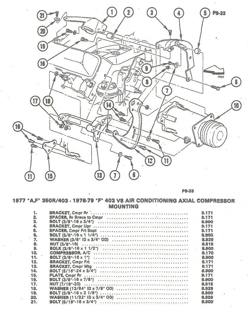 403 AC Compressor mounting diagram
 by
Aus78Formula, on Flickr
Here's your starting point, be it a 1977 350 or 1977-79 403 Oldsmobile, ready for brackets:
 403 AC compressor brackets not fitted
 by
Aus78Formula, on Flickr
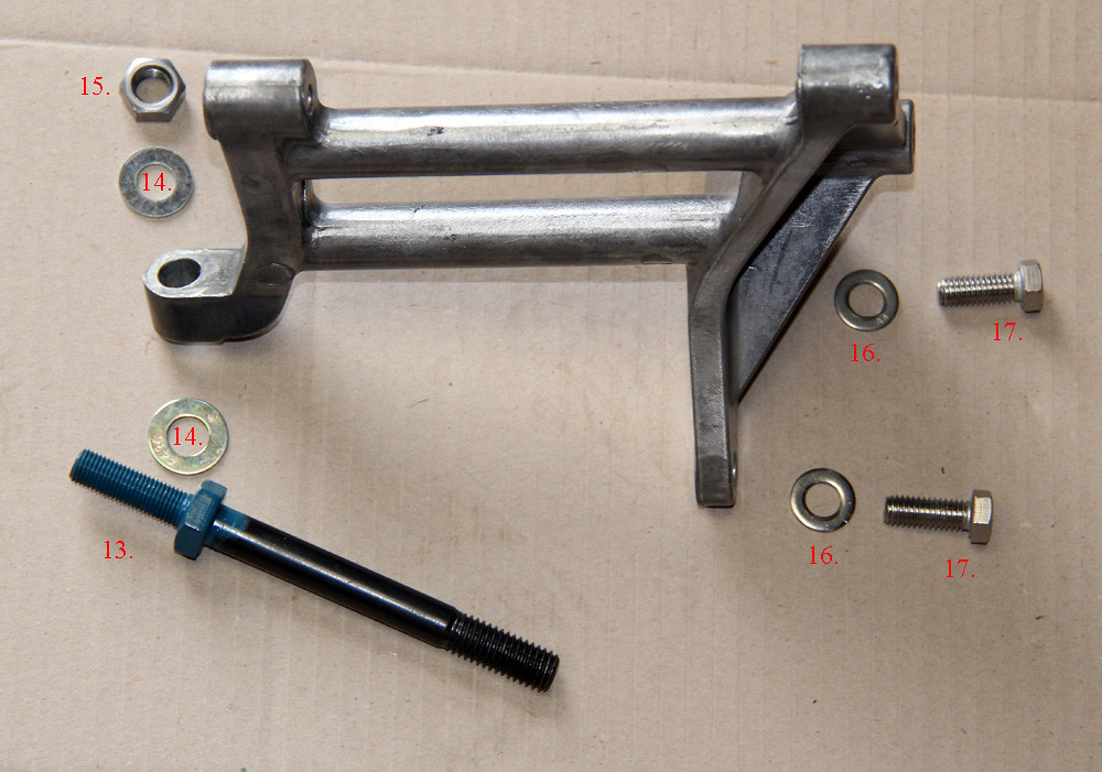
This is the first bracket to mount up, the aluminium support:
 403 AC compressor brackets lower support with bolts
 by
Aus78Formula, on Flickr
13. 1/2" UNC Head stud with 7/16" UNF Accsesory stud.
14. 7/16" Flat Washer.
15. 7/16" UNF Nut.
16. 3/8" Flat Washer.
17. 3/8" x 1-1/4" UNC Bolt.
(Note: Part numbers not in order of sequence, I started other photos first!)
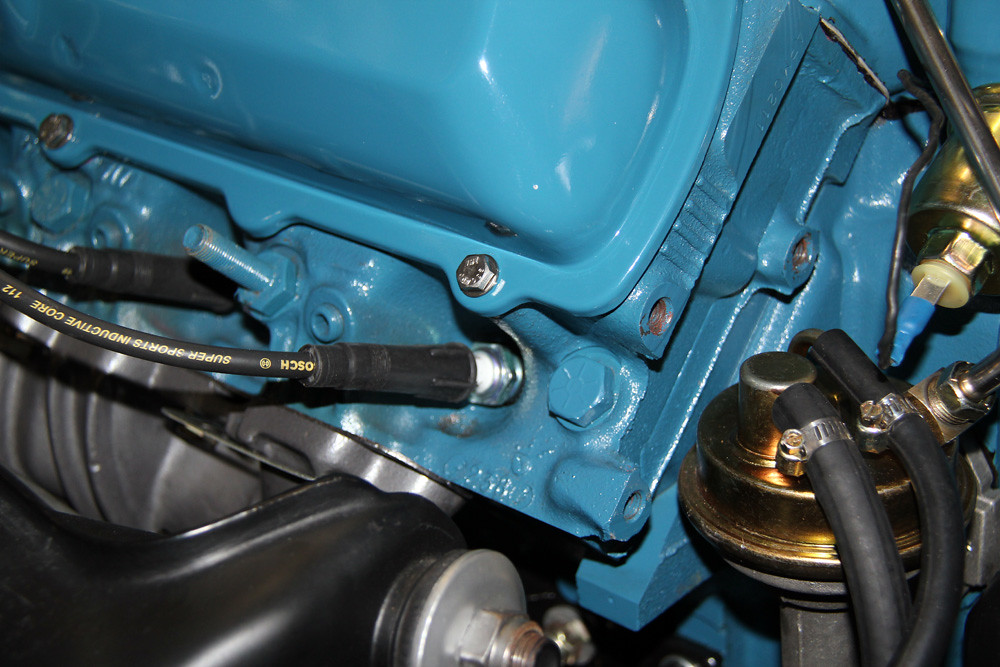
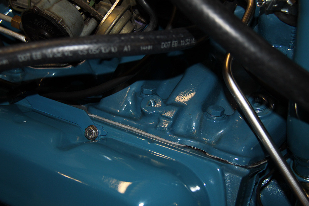
And here are the mounting holes for the alloy support bracket. You can see the two 3/8" UNC holes above the fuel pump with paint worn off and between the spark plugs is the head bolt with accessory stud:
 403 AC compressor brackets head mounting holes
 by
Aus78Formula, on Flickr
And with the bracket fitted, 2 bolts/washers in the front, washers and nut on rear, just visible.
 403 AC compressor brackets lower support fitted
 by
Aus78Formula, on Flickr
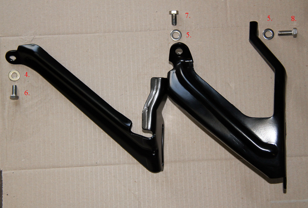
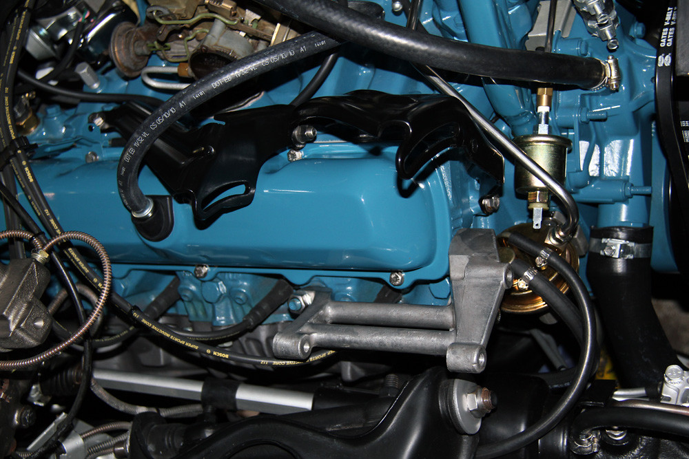
Next, we move onto the two V-shaped brackets that mount off the intake:
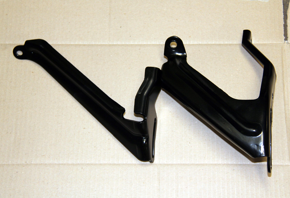 403 AC compressor brackets top brackets2
 by
Aus78Formula, on Flickr
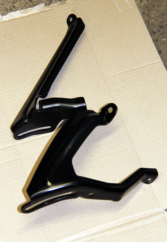 403 AC compressor brackets top brackets
 by
Aus78Formula, on Flickr
They are bolted together in the centre, it may help leaving this bolt loose until after fitting to intake or it can be hard to get it the holes lined up.
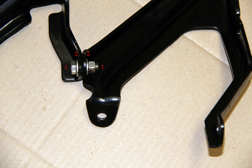 403 AC compressor brackets top brackets bolt
 by
Aus78Formula, on Flickr
1. 3/8" UNC x 1" Bolt. (Factory calls for 7/8" long but I have added a washer to each side)
2. 3/8" Flat Washer.
3. 3/8" UNC nut.
With the two brackets combined we then bolt it to the intake manifold, here's the fasteners:
 403 AC compressor brackets top brackets with bolts
 by
Aus78Formula, on Flickr
4. 5/16" Flat Washer.
5. 3/8" Flat Washer.
6. 5/16" UNC x 3/4" Bolt.
7. 3/8" UNC x 3/4" Bolt.
8. 3/8" UNC x 1" Bolt.
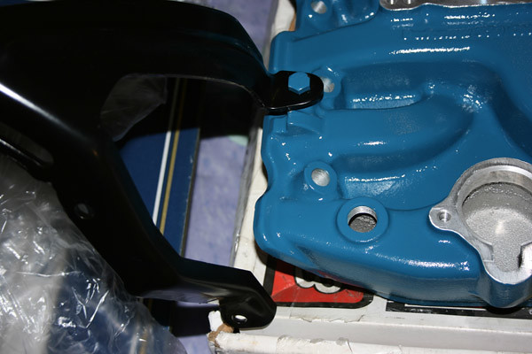
The Edelbrock Performer intake uses the same stock #16 cast iron intake mounting points for A/C, however there are some minor clearance issues with the F-body brackets and some molded on detail and runners. Here's some early photos of how I overcame it before the engine was even built:
In this photo the bracket is sitting up in the air, the cast triangular block is fouling it more than it actually looks:
 403 AC bracket manifold
 by
Aus78Formula, on Flickr
Simply file it down flat until it is level or below the mounting pad:
 403 AC bracket mod1
 by
Aus78Formula, on Flickr
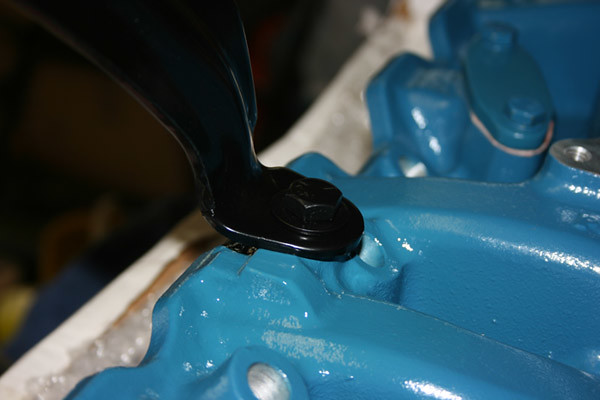
This is the rear bracket mount, looking from behind the distributor. It is already modified in this photo, the corner of the bracket rested on top of the intake runner. I simply cut the underside of the bracket flush and level with the runner, partly hidden in the shadow:
 403 AC bracket mod2
 by
Aus78Formula, on Flickr
Back to standard assembly...!
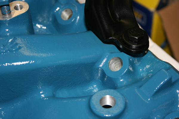
This is the front intake mounting hole for 3/8" Bolt. You can see the wear-mark groove on the modified pad to the right of the bolt hole where brackets have been test fit in the past:
 403 AC compressor brackets intake mount1
 by
Aus78Formula, on Flickr
And the Rear bracket mount to intake, for 5/16" Bolt.
403 AC compressor brackets intake mount1 by
Aus78Formula, on Flickr
And with the top brackets installed on intake, and bolt into front of head. Once these 3 bolts are started you can tighten the bolt that holds the two brackets together, then finish tightening the other 3 mounting points fully.
 403 AC compressor brackets top and bottom fitted
 by
Aus78Formula, on Flickr
Next are the brackets that mount to the compressor itself. Originally, the threaded holes in the compressor ends were Imperial but later models switched to the Metric equivalent. If you use a rebuilt unit like I did here, you could get Imperial or Metric so be sure to check, I have included both equivalent sizes.
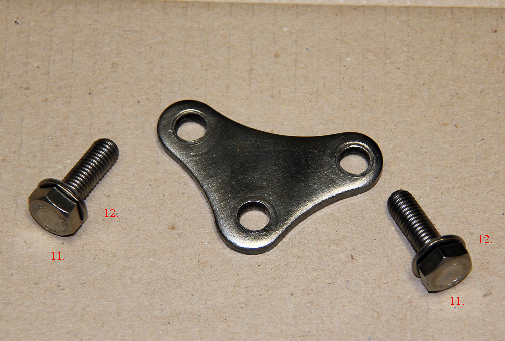
This small triangular bracket mounts to the rear base of the compressor. The 3rd hole faces downwards and meets the alloy bracket mounted onto the head earlier. Although similar brackets used on different models, this is Olds specific and often tossed with the compressor, easily lost. I have a spare should anyone need a tracing to make one from scratch.
 403 AC compressor brackets rear mount
 by
Aus78Formula, on Flickr
11. 3/8" UNC x 1" Bolt (M10 x 30mm) Factory manual calls for shorter bolts that only thread half way through the alloy, best to use it all for strength.
12. 3/8" Flat Washers (M10 Flat Washers)
* (Not shown here but the 3rd bolt hole uses 3/8" UNC x 1-1/2" Bolt and Flat Washer for mounting to the alloy bracket shortly. Again, the factory only called for a bolt that went half way through the thread alloy!)
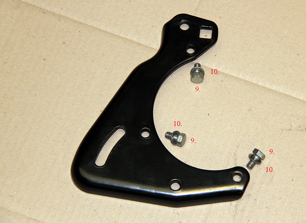
This is the front surround bracket for the compressor, again a mixture of Imperial and Metric threads so check first:
 403 AC compressor front bracket with bolts
 by
Aus78Formula, on Flickr
9. 5/16" UNC x 3/4" Bolt. (M8 x 15mm)
10. 5/16" Flat Washer. (M8 Flat Washer)
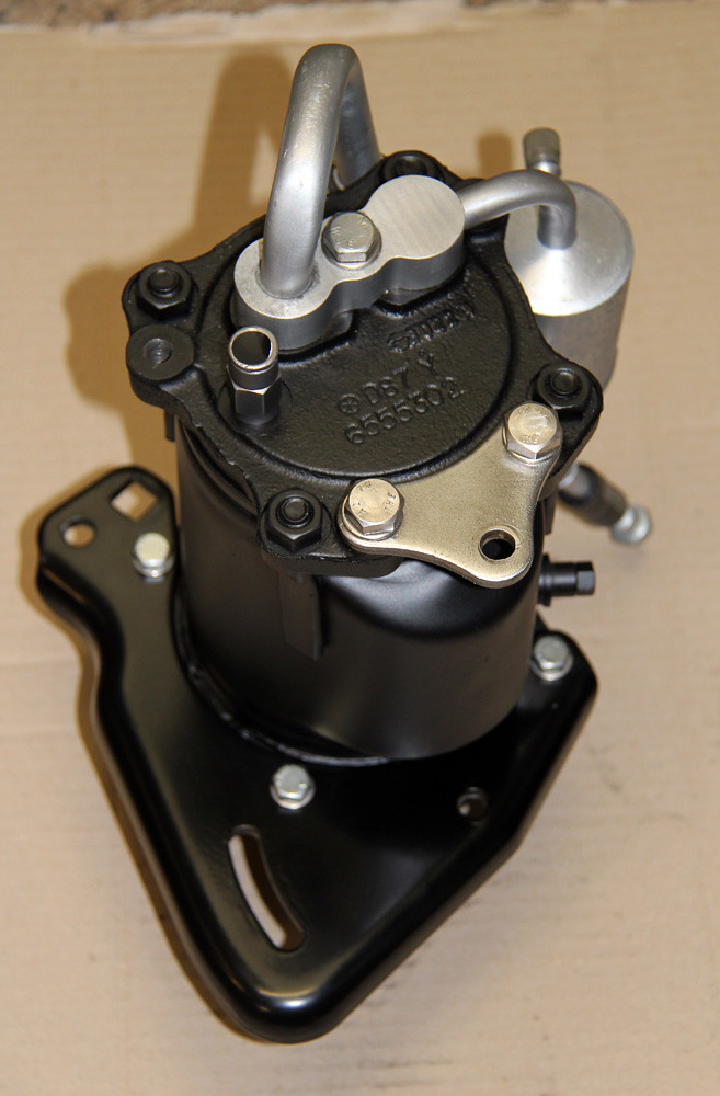
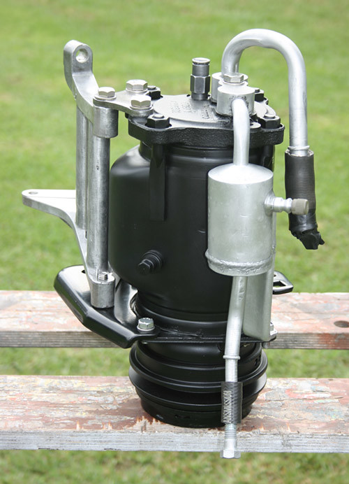
And the compressor complete with mounted triangle bracket and front surround bracket. Both brackets bolt from the rear into the compressor itself.
 403 AC compressor brackets fitted
 by
Aus78Formula, on Flickr
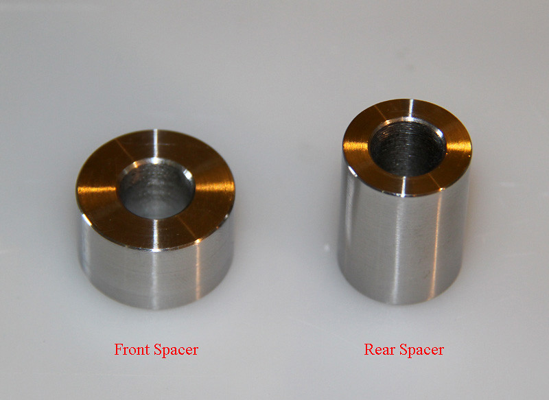
There are two spacer tubes, front and rear of the compressor. These both have a clearance hole for 3/8" (or M10). I machined mine up to suit required lengths as didn't have the original spacers. You may find you need a flat washer as a shim if you use a spacer that is too short.
 403 AC compressor spacers
 by
Aus78Formula, on Flickr
Front Spacer : Diameter 25mm, Length 15mm, Bore 7/16" / 11mm.
Rear Spacer : Diameter 20mm, Length 27mm (One original spacer was apparently 25mm / 1" long, I adjusted mine as required), Bore 7/16" / 11mm.
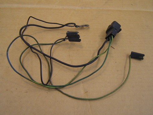
Here's the Oldsmobile A/C compressor loom. The twin-terminal plug goes to the compressor clutch, the single ring terminal is the earth that mounts to the front compressor support bracket. The long green wire is the idle-solenoid on the carburetor, increases idle when A/C is on. The three-terminal plug sits under the top brackets on the valve cover, connects to the rest of the A/C and Heater harness that is secured by the wire retainer on the valve cover bolt.
 403 AC compressor loom
 by
Aus78Formula, on Flickr
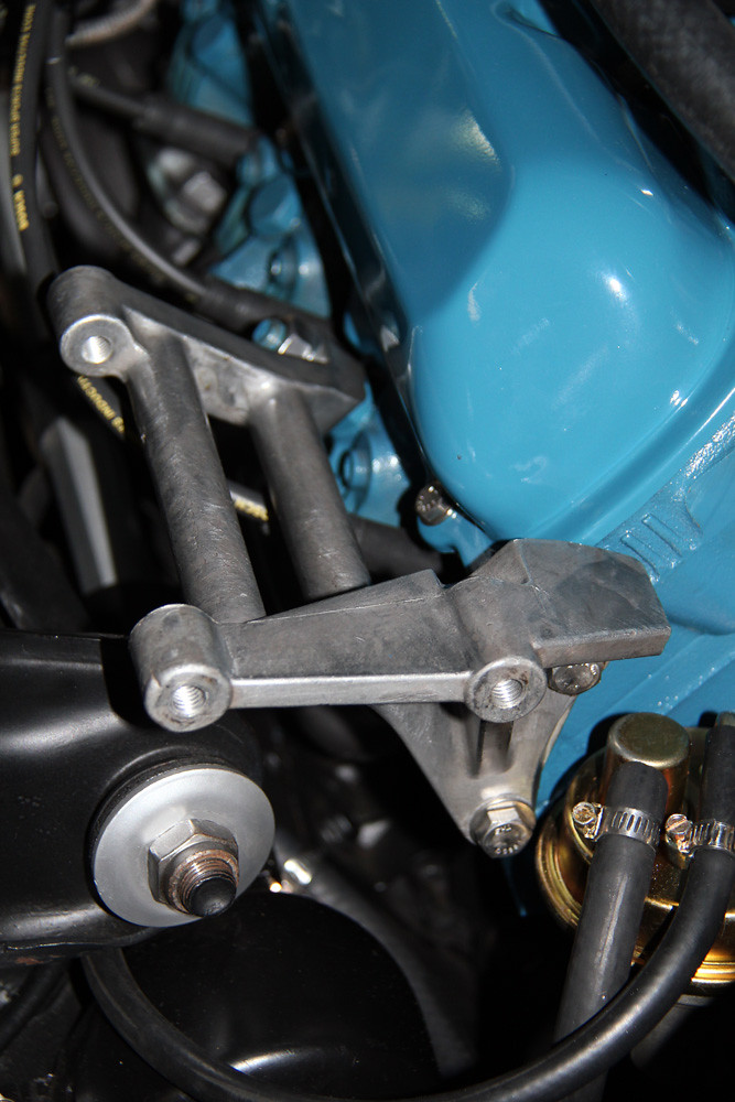
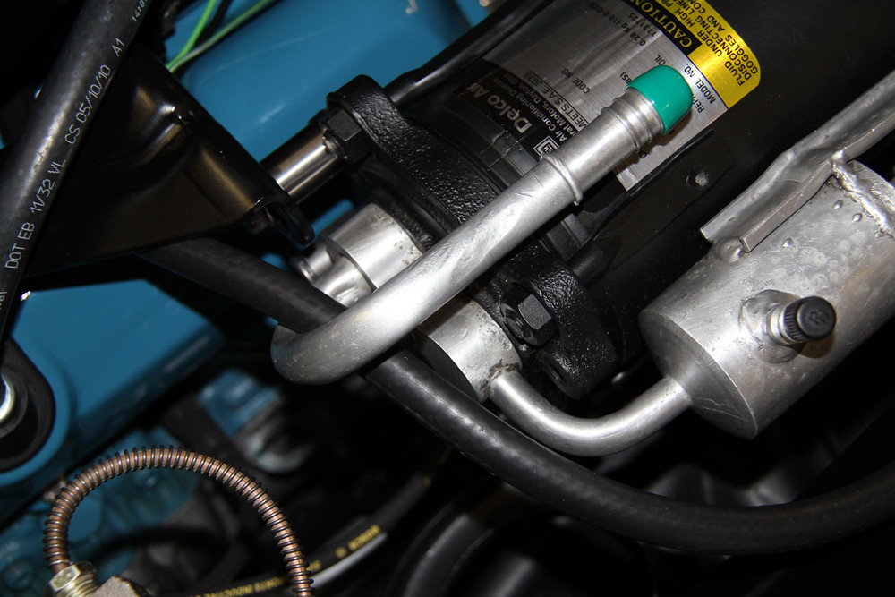
Finally, the compressor assembly can be mounted onto the alloy support bracket. The rear base of the Triangular bracket bolt to secure is 3/8" UNC x 1-1/2" Bolt and 3/8" Flat Washer. The 3/8" fuel hose runs to the charcoal canister on 78-79 models, maybe some 77. Diagrams show it simply runs around behind the compressor, I like to keep it off the valve covers by routing like this over the rear hose pipe for support.
 403 AC compressor rear
 by
Aus78Formula, on Flickr
There are two bolts fitted through the front of the compressor surround bracket into the alloy support bracket. These are both 3/8" UNC x 1-1/2" Bolts with a matching Flat Washer on each. Again, the factory bolts are shorter and use only part of the alloy threaded hole. These bolt/s can be seen in some of the completed photos below.
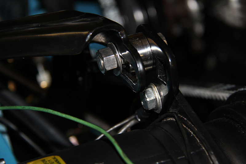
Finally, the spacers can be fitted between the top brackets and bolts fitted to secure. The front spacer bolt is 3/8" UNC x 1-1/2" with 3/8" Flat Washer, with another flat washer and nut on rear. You can see where the earth for the Wiring harness mounts also.
 403 AC compressor front spacer
 by
Aus78Formula, on Flickr
The rear spacer bolt is 3/8" UNC x 2" with 3/8" Flat Washer (M10 x 50mm and M10 Flat Washer).
 403 AC compressor rear2
 by
Aus78Formula, on Flickr
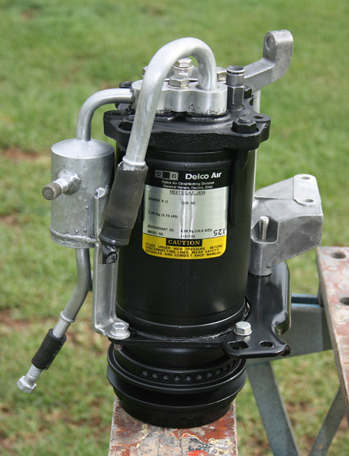
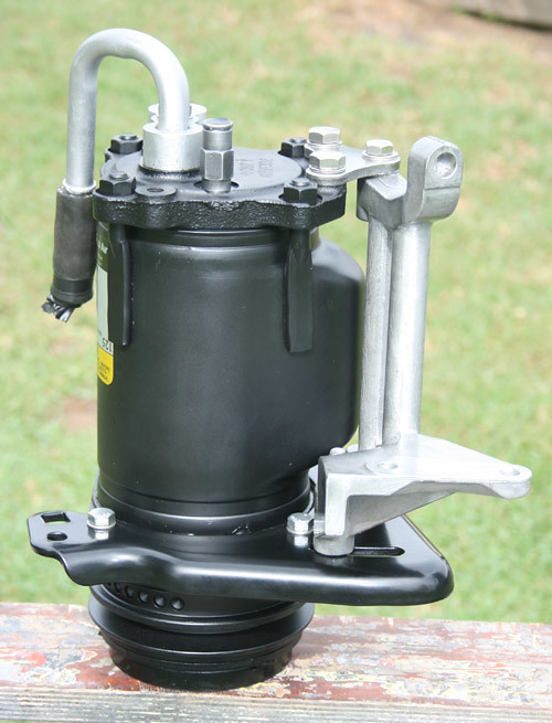
The wiring loom and fanbelt can be fitted now also. Depending on where the clutch was fitted you may end up with the plug closer to the earth terminal giving extra length for your wiring harness down the valve cover. The installed unit should look something like this:
 A6 Compressor and brackets1
 by
Aus78Formula, on Flickr
 A6 Compressor and brackets2
 by
Aus78Formula, on Flickr
 A6 Compressor and brackets3
 by
Aus78Formula, on Flickr
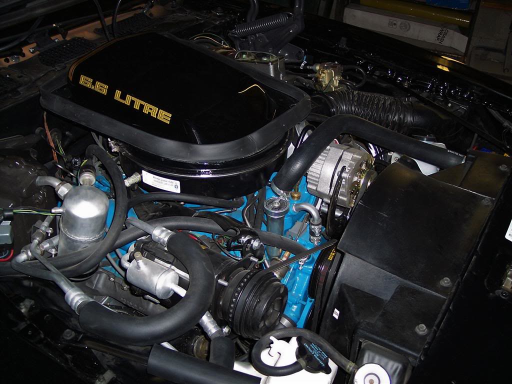
There are two variations of the fan-belt routing depending on if the engine was fitted with a Smog/Air-pump from factory for emissions. Those without the pump used the second diagram here, the belt being 60" / 1530 mm long and ran around both water pump and crank pulleys on the rear grooves. Of course, even if the smog pump is long gone, the pulley type remains. If unsure, the slighter curved oil filler tube with flat front is for smog pump clearance when installed. The shorter tube that's simply round and straight is the non-pump version.
The engines with pumps fitted from factory used the 4th layout of fan-belt. It only ran around the crank pulley and was 57" / 1450mm long. This was due to the water pump pulley being shorter in offset by the depth of one belt groove and enabled a 4th accessory to be used on the front. My engine photos are of this 4th diagram, still has the same pulleys but pump removed.
 403 accessory pulley diagram
 by
Aus78Formula, on Flickr
Here's a blurry photo showing the smog-pump belt version running behind the water pump pulley to crank only:
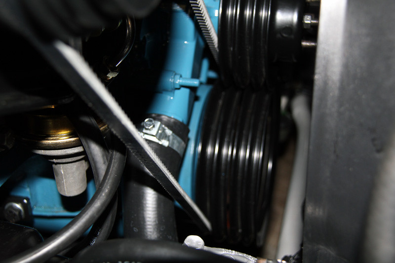 AC Compressor adjustment4 1450 belt
 by
Aus78Formula, on Flickr
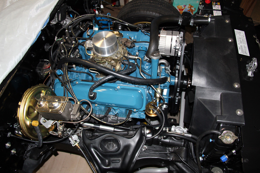
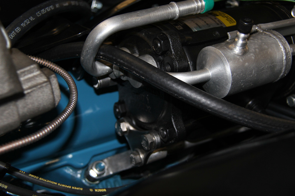
And here's a beautifully restored engine with original non-pump setup, belt running around water pump as well. Saved sample photo off net. Note the straight oil filler tube mentioned above for non-smog pump vehicles.
 403 79 TA restored engine bay3
 by
Aus78Formula, on Flickr
Hopefully, some of that assists in fitting your brackets and making sense of the factory diagrams and parts required. Thanks also to Edward and Steve for their input. If any has been left out or not clear let me know so I can correct or clarify.
The alloy muffler unit on top of the compressor is a late-78/79 model change. Pre-79 used the separate muffler mounted on a shelf bracket above the vacuum canister which mine would have had originally. But since I was missing the lot, I used what I could find, this was before hoses and parts could be purchased from restoration shops with correct parts. It doesn't affect brackets.


